N. J. Kidnera, S. Ibaneza, M. M. Seabaugha, and S. L. Swartza
a Nexceris LLC, Lewis Center, Ohio 43035, USA
In the development of solid-oxide fuel cells, high-performance coatings are essential to successful commercialization. Electrode coating technologies allow the cost-effective deposition of anode and cathodes on cell components at high volumes and high precision. Further, catalytic and corrosion resistant coatings for common steel alloys find application in gas delivery and fuel reforming components of the balance-of-plant. Such corrosion-resistant alloys are also combined with conductive and insulating oxide protective layers to make low-cost steel interconnectors corrosion-resistant at SOFC operating temperatures while maintaining low contact resistance and minimizing Cr volatilization.
Many of the first-generation coating technologies that have found commercial implementation were designed for cell and stack operating temperatures of 750°C and higher. In this paper, Nexceris will report on the development of new formulations designed to meet the needs of lower operating temperature SOFCs.
Introduction
Solid Oxide Fuel Cells (SOFCs) are environmentally clean, quiet, and highly efficient devices for generating electricity and heat from a variety of hydrocarbon fuels including diesel, natural gas, and biomass. Fuel cells have emerged in the past decade as one of the most promising new technologies for meeting ever increasing energy needs in the 21st century. SOFC systems are beginning to find application in markets throughout the world. Premium power products (uninterrupted power for datacenters and mobile systems for military) are providing the first market niches, while new utility strategies requiring distributed micro-grid power generation and energy storage promise excellent opportunity for product developers. To reach larger markets, SOFC systems must provide a better dollars/kilowatt ratio through performance improvements that reduce manufacturing complexity and cost, and increase durability and operating lifetime.
Current commercially developed SOFC systems operate at stack operating temperatures of 750 °C or higher. Reducing the stack operating temperature to the 600°C range (low-temperature SOFCs, LT-SOFC), addresses high-system and operating costs, and poor durability, allowing for greater commercial acceptance, especially for dynamic applications such as automotive and load-following applications where short start-up and shut-down times are required.
Reducing operating temperatures allows SOFC designers to replace expensive high-temperature alloys with inexpensive metals for electrical interconnection and balance-of-plant (BoP). While degradation mechanisms associated with materials compatibility (e.g., CTE mismatch) and high-temperature corrosion are reduced with lower operating temperatures, the required high-activity cathodes are highly sensitive to poisoning through chromium vaporization, which has been demonstrated at temperatures as low as 600°C (1). There is therefore increased importance and need for high-quality, low-temperature compatible protective coatings to inhibit chromium vaporization and achieve the required SOFC lifetime target.
For SOFCs operating at temperatures of 750°C and higher, a number of protective coatings have been developed. For protection of the cathode active-area of metallic interconnects, electrical conductive coatings are required. One of the most promising is the manganese cobaltite spinel oxide (Mn,Co)3O4 (MCO) (2). MCO demonstrates excellent thermal expansion match to ferritic stainless steel interconnects, high electrical conductivity, and better capability to prevent chromium volatilization than other oxide coatings (3). The MCO coating acts as an effective barrier to both inward oxygen ion diffusion and outward chromium migration.
Nexceris has successfully developed a commercial MCO-based coating technology (referred to as ChromLokTM) that demonstrates excellent protection for metallic interconnects used in high- and intermediate-temperature SOFCs (4). By design, conductive coatings for steels provide low contributions to the overall stack resistance (ASR less than 50 mW-cm2) at these operating temperatures. However, as stack operating temperatures push to the 600°C-700°C range, new protective coatings are required that achieve similar resistances at lower temperatures.
In this study, a newly developed lanthanum-nickel-cobalt (LNC) perovskite coating is introduced which has been tailored to provide the low resistances required for LT-SOFC operation (5). The new coating is amenable to the same cost-effective aerosol-spray deposition (ASD) process as Nexceris’ ChromLokTM technology. Microstructural analysis and electrical performance are presented that demonstrate the suitability of LNC over MCO for LT-SOFCs coating applications.
Experimental Details
Lanthanum nickel cobalt perovskite oxide (LNC) powder, composition La(Ni0.6Co0.4)O3, was produced from starting oxides through standard solid-state processing. The LNC powder was then made into a solvent-based suspension, with solids loading and viscosity targeted for aerosol-spray deposition (ASD). LNC coatings were applied to Crofer 22APU substrates (20 mm x 20 mm) by ASD using an Ultrasonic Systems Prism 300 coating system. One spray/dry pass was required to achieve the target 5 mm coating thickness. Coated samples were then controlled fired to achieve dense, adherent coatings.
Electrical Testing
The area-specific resistance (ASR) of double-sided LNC coated Crofer 22APU was measured using a four-terminal DC technique. Samples were provided with LSM conductive pads for electrical contact. Platinum leads and mesh were bonded to the pads with LSM ink and cured. The samples were electrically tested in humidified air (3 % H2O), with an applied current density of 0.5 A/cm2 at temperatures between 500°C and 800°C.
Microstructural Characterization
The MCO coating microstructure was evaluated by cross-sectional scanning electron microscopy (SEM) and compositional energy dispersive spectroscopy (EDS), using a JEOL JSM840-A Scanning Electron Microscope and in conjunction with an EDS system manufactured by PGT/Bruker.
Results and Discussion
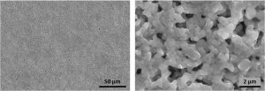
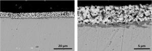
The microstructure of the LNC coating is shown in top-down (Figure 1) and cross-section (Figure 2) SEM images. The LNC coating is uniform with no evidence of cracking or other coating defects. The cross-section images in Figure 2 show that the ASD process is able to demonstrate a uniform micron level coating thickness. To improve the densification of the LNC coating, the incorporation of various sintering aids into the coating formulation is under investigation. It is anticipated that these modifications will achieve the dense LNC coating necessary to be an effective barrier to outward chromium migration from the steel surface.

Figure 1. Top-down scanning electron microscopy (SEM) images of LNC coating.

Figure 2. Cross-section SEM images of LNC coating on Crofer 22APU
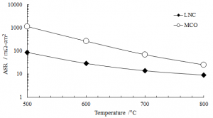
The effect of temperature on the electrical resistance (ASR) of LNC and MCO coatings over the temperature range 500°C to 800°C is shown in Figure 3. At high temperatures (800°C), both coatings demonstrate low ASR (LNC: 9.1 mW-cm2, MCO: 25 mW-cm2). However, as the temperature is lowered, the ASR of the MCO coating increases significantly to greater than 250 mW-cm2 at 600 C whereas the ASR of the LNC coating increases slowly and it continues to demonstrate excellent conductivity (LNC at 600 C: 29 mW-cm2). This order of magnitude improvement in ASR at LT-SOFC operating temperature illustrates the benefit of tailoring coating formulations for low-temperature use and not relying on high-temperature solutions.

Figure 3. Electrical area-specific resistance (ASR) versus temperature for symmetrically LNC and MCO coated Crofer 22APU substrates in humidified air with an applied current density of 0.5 A/cm2.
Figure 3. Electrical area-specific resistance (ASR) versus temperature for symmetrically LNC and MCO coated Crofer 22APU substrates in humidified air with an applied current density of 0.5 A/cm2.
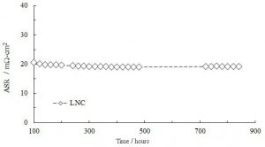
After the completion of thermal cycling (~ 100 hours), the coated LNC sample from Figure 3 was left on long-term, isothermal ASR testing at 700°C in humidified air as shown in Figure 4. The gap in data between 500 and 700 hours was caused by a power outage. The sample stayed at temperature but no data was collected during this period. The LNC coating demonstrates excellent stability with the ASR remaining unchanged over 700 hours.
Conclusions
The results show that for LT-SOFC applications the coating solutions developed for high temperature SOFC applications do not transfer, and new coatings, tailored to achieve lower electrical resistances, are required. The LNC perovskite oxide coating presented demonstrates an order of magnitude improvement in electrical resistance at LT-SOFC operating temperatures. Utilizing the same process operations as Nexceris’ ChromLokTM technology, this LNC coating provides cost-effective and scalable protection to metallic components used in LT-SOFC systems.

Figure 4. Long-term Electrical area-specific resistance (ASR) of LNC coated Crofer 22APU substrates at 700 °C in humidified air with applied current density of 0.5 A/cm2.
Acknowledgments
This material is based upon work supported by the U.S. Department of Energy,
Office of Science, Office of Fossil Energy, under Award Number DE-SC0008203.
Disclaimer: “This report was prepared as an account of work sponsored by an agency of the United States Government. Neither the United States Government nor any agency thereof, nor any of their employees, makes any warranty, express or implied, or assumes any legal liability or responsibility for the accuracy, completeness, or usefulness of any information, apparatus, product, or process disclosed, or represents that its use would not infringe privately owned rights. Reference herein to any specific commercial product, process, or service by trade name, trademark, manufacturer, or otherwise does not necessarily constitute or imply its endorsement, recommendation, or favoring by the United States Government or any agency thereof. The views and opinions of authors expressed herein do not necessarily state or reflect those of the United States Government or any agency thereof.”
References
- Falk-Windisch, J. E. Svensson, and J. Froitzheim, J. Power Sources, 287, 25 (2015).
- Yang, G. Xia, S.P. Simner and J.W. Stevenson, J. Electrochem. Soc., 152, 1896 (2005).
- Larring and T. Norby, J. Electrochem. Soc., 47, 3251 (2000).
- J. Kidner, S. Ibanez, G. Arkenberg, M. M. Seabaugh, and S. L. Swartz, ECS Trans., 68, 1569 (2015).
- M. Seabaugh, S. Ibanez, and S. L. Swartz., US Patent 9054348 B2, (2015).
Let us help make your stacks last longer. | |
|---|---|
Contact us for a free interconnect coating consultation with our SOFC experts and discover ways to improve the lifetime of your SOFC stacks. | |
